91/4” 121/2” 11”
FILE #E21609
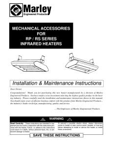
SRA-DS Series Model B Fan Forced Wall Heaters
103/8”
4” 1”
Installation & Maintenance Instructions Dear Owner,
Congratulations! Thank you for purchasing this new heater manufactured by Marley Engineered Products. You have made a wise investment selecting the highest quality product in the heating industry. Please carefully read the installation and maintenance directions shown in this manual. You should enjoy years of efficient heating comfort with this product from Marley Engineered Products... the industry’s leader in design, manufacturing, quality and service.
!
WARNING
Read Carefully - These instructions are written to help
5.
you prevent difficulties that might arise during installation of heaters. Studying the instructions first may save you considerable time and money later. Observe the following procedures, and cut your installation time to a minimum.
6.
To reduce risk of fire or electric shock:
1. 2.
3. 4.
Disconnect all power coming to heater at main service panel before wiring or servicing. All wiring must be in accordance with the National and Local Electrical Codes and the heater must be grounded as a precaution against possible electric shock. Verify the power supply voltage coming to heater matches the ratings printed on the heater nameplate before energizing. This heater is hot when in use. To avoid burns, do not let bare skin touch hot surfaces.
7. 8. 9.
... The Employees of Marley Engineered Products
Do not insert or allow foreign objects to enter any ventilation or exhaust opening as this may cause an electric shock, fire,or damage to the heater. Do not block air intakes or exhaust in any manner. Keep combustible materials, such as crates, drapes, etc., away from heater. Do not install behind doors, furniture, towels, or boxes. A heater has hot and arcing or sparking parts inside. Do not use it in areas where gasoline, paint or flammable liquids are stored. Use this heater only as described in this manual. Any other use not recommended by the manufacturer may cause fire, electric shock, or injury to persons. This heater is not approved for use in corrosive atmospheres such as marine, green house or chemical storage areas.
SAVE THESE INSTRUCTIONS 1
IMPORTANT !
!
!
WARNING
TO PREVENT POSSIBLE WIRING DAMAGE CUT EXCESS SUPPLY WIRE INSIDE BACKBOX TO PROVIDE APPROXIMATELY 6 INCHES FOR CONNECTION TO HEATER LEADS. AFTER CONNECTIONS ARE MADE, MAKE SURE CONNECTIONS ARE TIGHT AND ALL WIRING IS POSITIONED AWAY FROM FAN BLADE AND HEATING ELEMENT.
TO PREVENT HAZARD OF FIRE OR ELECTRICAL SHOCK, DO NOT INSTALL WITHOUT BACK BOX.
CAUTION
!
CAUTION
!
CAUTION
NOTE: Lead holes for a #8 sheet metal screw have been provided in the sides of the back box. After the finished wall has been put up, drive a # 8 (m4) sheet metal screw (recommended 1” long) through the side of the box not mounted to the stud. This will prevent the back box from pulling out when installing the heater assembly. (See Figure 1)
FOR WALL MOUNTING, DO NOT INSTALL HEATER CLOSER THAN 2" (51mm) TO THE FLOOR OR ANY ADJACENT WALL SURFACE. DO NOT INSTALL CLOSER THAN 36" (915mm) TO THE CEILING.
!
CAUTION
AN ELECTRICAL SHOCK, FIRE OR WATER DAMAGE COULD RESULT IF WIRING OR PIPING IS DAMAGED DURING CUTTING. MAKE SURE ALL WIRING AND PIPING ARE CLEAR OF AREA BEFORE CUTTING.
THE HEATER IS HOT WHEN IN USE. DO NOT INSTALL THE HEATER BEHIND DOOR, BEHIND TOWEL RACK, IN CLOSET, WHERE CURTAINS OR DRAPES COULD TOUCH OR BECOME SCORCHED BY HEATER, OR WHERE AIRFLOW TO HEATER MAY BE OBSTRUCTED. KEEP ELECTRICAL CORDS, BEDDING, FURNITURE AND OTHER COMBUSTIBLES AWAY FROM HEATER.
INSTALLATION OF BACK BOX IN EXISTING CONSTRUCTION 1. Carefully mark and cut a hole measuring 9-3/8" (235mm) wide by 111/8" (283mm) long. One edge of the hole must be cut along the edge of a stud.
GENERAL
The heater is designed for recessed installation in 2” X 4” (50mm X 101mm) stud or larger wall using the wall box provided. The heater may also be surface mounted by using the Surface Mounting Frame, Model SRASM or semirecess mounted by using a SRAS1 (for 1” (25 mm) recess frame) or a SRAS2 (for 2” (50mm) recess frame). All three accessories are ordered separately. The heater may be wired with standard building wire (60°C). Refer to specification chart (see pg. 4) for correct supply voltage and wire size.
2. Proceed to No. 1 through 5 (Installation of Wall Box in New Construction).
FIELD CONVERSION FOR LOWER WATTAGE RATING
NOTE: Refer to specification chart for lower wattage ratings which are available.
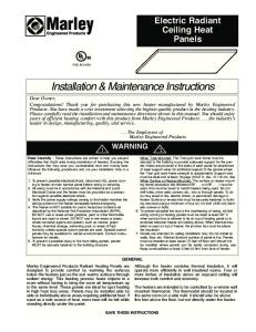
To convert heater to lower wattage rating, completely remove red jumper wire from both heating elements (See Figure 2). Discard this jumper. Be sure remaining wires are securely connected.
NOTE: The optimum mounting height for this heater is 18" to 24" (450 to 600mm) from floor to bottom of back box. Do not install closer than 2”(50mm) from the floor. Back box may be mounted such that discharge portion of grille can be oriented down, left, right, or up.
For surface or semi-recess mounting, consult Installation Instructions packed with SRASM, SRAS1, SRAS2
Remove red jumper for lower wattage rating
INSTALLATION OF WALL BOX IN NEW CONSTRUCTION
NOTE: If the finished wall surface is already up, follow instructions for “INSTALLATION OF BACK BOX IN EXISTING CONSTRUCTION”.
Figure 2
1. Determine which side of the back box is to be mounted against a stud and bend the tabs at the rear corners out 90 degrees so that the back box will be square with the stud after installation. (See Figure 1).
CAUTION
2. Remove one of the knockouts on socket side of the back box and install a cable or conduit connector.
DO NOT USE A REMOTE THERMOSTAT WITH THIS HEATER. BUILT IN THERMOSTAT CYCLES THE HEATING ELEMENT ONLY. FAN DELAY CONTROL AUTOMATICALLY TURNS FAN ON AND OFF, AND PROVIDES A FAN DELAY OFF FEATURE TO REMOVE RESIDUAL HEAT AFTER THERMOSTAT HAS TURNED HEATING ELEMENTS OFF. WIRING OF HEATER IN ANY MANNER WHICH DEFEATS THE FAN DELAY OFF FEATURE CAN RESULT IN OVERHEATING AND PERMANENT DAMAGE TO HEATER, AND WILL VOID THE WARRANTY.
3. Position back box against side of studs and secure using nails or screws as shown in Figure 1.
NOTE: The back box must be installed with the front edge flush with the finished surface. 4. Run power supply cable through the connector, leaving about 6” of wire inside the box. 5. Connect the supply cable ground wire to green ground screw provided.
INSTALLATION AND WIRING OF HEATER / FAN ASSEMBLY 1.
Following wiring diagram (Figure 3) connect supply wiring to heater leadwires in back box.
NOTE: For 120 and 277 volt heaters connect the white neutral supply lead to the heaters white pigtail lead, and connect the black supply lead to the heater black pigtail lead. For 208 and 240 volt heaters change the color of the heaters white pigtail lead to black by wrapping with black electrical tape. (Most electrical codes require the supply leads to be connected to black leads). Then connect the two black supply leads to the two black receptacle leads.
Figure 1 2
Figure 4
7. It may be necessary to readjust thermostat a time or so until exact comfort level is attained. Rotation in the clockwise direction will increase the amount of time the heater will produce heat. Rotation in the counterclockwise direction will reduce the amount of time the heater is on.
Figure 3
NOTE: For best results, the heater should be left “ON” constantly during the heating season as the thermostat, when properly set, will maintain the desired temperature. In the full counter-clockwise position the heater will remain off until the room temperature drops well below freezing.
2. Secure supply ground wire under green ground screw in back box.
3. Insert wiring plug from heater/fan assembly into socket in back box. a
CAUTION
!
MAINTENANCE AND CLEANING
Your heater is designed for years of trouble-free operation and requires no special maintenance other than occasional cleaning. The motor is permanently lubricated.
BE SURE ALL WIRING IS SECURELY ROUTED AWAY FROM FAN AND ELEMENT. 4. Fit heater/fan assembly into back box and secure in place with (2) screws provided through the center slots in the fan assembly.
Once each year, the heater should be cleaned to remove dust and other foreign material which has collected during the heating season, as follows:
NOTE: Use the screws provided by the factory to install fan deck to the back box.
1. Turn power off at main switch. 2. Remove thermostat knob.
INSTALLATION OF FRONT COVER (GRILLE) AND THERMOSTAT KNOB
3. Remove front cover by depressing plastic tabs with a flat bladed screwdriver as shown in Figure 4. Release both tabs on one side then rotate cover off of heater assembly.
1. The three grille parts are shipped assembled. Remove the top and bottom plastic pieces from the front cover. A flat blade screwdriver can be used to gently separate the front cover from the plastic pieces.
4. Use vacuum cleaner with brush attachment to remove dust and dirt that has accumulated in heater (especially around element and fan blade). Do not use water or any cleaners to clean heater components.
2. Attach the top and bottom plastic pieces to the heat deck using the four (4) screws provided in the parts bag.
5. Replace grille and thermostat knob.
3. Position the front cover so the four (4) holes on the side align with the tabs on the plastic pieces mounted on the heat deck.
6. Wipe grille clean with a damp cloth. DO NOT use waxes or any cleaners that leave a residue since these may discolor during heater operation.
4. Hook the front cover over the tabs on one side then rotate the front cover into place making sure that all four tabs are snapped onto the front cover.
7. Turn the main line switch on at the switch panel to restore power to heater. The heater is now ready for another season of operation.
HEATER CHECKOUT AND OPERATION
OPERATIONAL NOTICE
1. After heater is completely assembled, push the disconnect switch to the “on” position and rotate thermostat knob counterclockwise until control stops. This is the minimum heat setting.
Your heater is equipped with an automatic reset high limit control that will automatically turn the heater off to prevent a fire if the heater overheats. Should this occur, the indicator light will illuminate and will continue to shine until the limit resets.
2. Turn power supply to heater “ON” at main switch panel.
3. Heater should not operate. If it operates, disconnect power and recheck wiring.
!
4. Rotate thermostat clockwise until it stops (maximum heat setting) and wait at least 2 minutes. Fan control will delay fan coming on until element is warm.
THE ILLUMINATED INDICATOR LIGHT SIGNIFIES THE HEATER HAS BEEN SUBJECTED TO SOME ABNORMAL CONDITION. CHECK HEATER TO INSURE THAT IT HAS NOT BEEN BLOCKED IN ANY MANNER (IF SO, REMOVE BLOCKAGE). IF THERE IS NO INDICATION OF BLOCKAGE, IT IS RECOMMENDED THE HEATER BE CHECKED BY A REPUTABLE ELECTRICIAN OR REPAIR SERVICE TO INSURE THE HEATER HAS NOT BEEN DAMAGED.
5. If heater and fan do not come on, disconnect power and check wiring. 6. Allow heater to continue to operate until room temperature reaches desired comfort level. Then rotate thermostat knob counterclockwise slowly until thermostat clicks off. Fan will continue to operate for a minute or so until element cools. a
CAUTION
CAUTION
!
IF FAN SHUTS OFF IMMEDIATELY, THERMOSTAT WIRING IS INCORRECT AND MUST BE CHANGED. FAN MUST DELAY SHUTTING OFF TO EXPEL RESIDUAL HEAT TO PREVENT PREMATURE AGING OF INTERNAL HEATER COMPONENTS THAT COULD LEAD TO A HAZARD OR PREMATURE FAILURE. 3
Specifications MODEL NO.
SRA1012DSB SRA1512DSB
VOLTS
AMPS
WATTS
120
8.40 4.20
1000 500
3413 1706
14AWG
15.0
1800
6143
12 AWG
120
SRA1812DSB
120
SRA2024DSB
208
SRA2027DSB
SRA1527DSB SRA****IF SRBB SRASM SRAS2 SRAS1
SRADS
SRAFCTP
IMPORTANT INFORMATION
240
277 240 277 240
12.50 6.25 8.40 4.20 7.30 3.61
7.30 3.61 6.25 3.20
5.5 2.75 4.7 2.35
1500 750 2000 1000 1500 750 2000 1000 1500 750 1500 750 1125 562
BTU/HR
5120 2560 6826 3413 5120 2560 6826 3413 5120 2560 5120 2560 3840 1920
WIRE SIZE
12AWG
14AWG
14AWG
NAMEPLATE
MODEL NO.
14AWG
Inner Frame (Fan Deck Assembly & Grille) Only Back Box Only - For All Above Heaters Surface Mounting Frame (Accessory) Order Separately 12-1/2”H X 10-3/8”W X 4”D 2” Recess Mounting Frame (Accessory) Order Separately 12-1/2”H X 10-3/8”W X 2”D 1”Recess Mounting Frame (Accessory) Order Separately 12-1/2”H X 10-3/8”W X 1”D 20 Amp-2 Pole Disconnect Switch Kit (Accessory) Order Separately
SRA2024DSB
DATE CODE
SMALL ROOM FAN FORCED HEATERS 2000/1000W @ 240VAC 60HZ 1500/750W @ 208VAC 60HZ
MUST BE USED WITH SR-BB BACK BOX. DO NOT OPERATE WITHOUT SR-FC SERIES FRONT COVER IN PLACE.
MARLEY ENGINEERED PRODUCTS BENNETTSVILLE, SC 29512
0695
774G LISTED ROOM HEATER
399726043
Tamper Proof Front Cover (Accessory Order Separately)
LIMITED WARRANTY
All products manufactured by Marley Engineered Products are warranted against defects in workmanship and materials for one year from date of installation, except heating elements which are warranted against defects in workmanship and materials for five years from date of installation. This warranty does not apply to damage from accident, misuse, or alteration; nor where the connected voltage is more than 5% above the nameplate voltage; nor to equipment improperly installed or wired or maintained in violation of the product’s installation instructions. All claims for warranty work must be accompanied by proof of the date of installation.
The customer shall be responsible for all costs incurred in the removal or reinstallation of products, including labor costs, and shipping costs incurred to return products to Marley Engineered Products Service Center.Within the limitations of this warranty, inoperative units should be returned to the nearest Marley authorized service center or the Marley Engineered Products Service Center, and we will repair or replace, at our option, at no charge to you with return freight paid by Marley. It is agreed that such repair or replacement is the exclusive remedy available from Marley Engineered Products.
THE ABOVE WARRANTIES ARE IN LIEU OF ALL OTHER WARRANTIES EXPRESSED OR IMPLIED. AND ALL IMPLIED WARRANTIES OF MERCHANTABILITY AND FITNESS FOR A PARTICULAR PURPOSE WHICH EXCEED THE AFORESAID EXPRESSED WARRANTIES ARE HEREBY DISCLAIMED AND EXCLUDED FROM THIS AGREEMENT. MARLEY ENGINEERED PRODUCTS SHALL NOT BE LIABLE FOR CONSEQUENTIAL DAMAGES ARISING WITH RESPECT TO THE PRODUCT, WHETHER BASED UPON NEGLIGENCE, TORT, STRICT LIABILITY, OR CONTRACT.
Some states do not allow the exclusion or limitation of incidental or consequential damages, so the above exclusion or limitation may not apply to you. This warranty gives you specific legal rights, and you may also have other rights which vary from state to state.
For the address of your nearest authorized service center, contact Marley Engineered Products in Bennettsville, SC, at 1-800-642-4328. Merchandise returned to the factory must be accompanied by a return authorization and service identification tag, both available from Marley Engineered Products. When requesting return authorization, include all catalog numbers shown on the products. HOW TO OBTAIN WARRANTY SERVICE AND WARRANTY PARTS PLUS GENERAL INFORMATION 1. Warranty Service or Parts 2. Purchase Replacement Parts 3. General Product Information
1-800-642-4328 1-800-654-3545 www.marleymep.com
Note: When obtaining service always have the following: 1. Model number of the product 2. Date of manufacture 3. Part number or description
Part No. 5200-2181-009
470 Beauty Spot Rd. East Bennettsville, SC 29512 USA
ECR 38595 12/09 4
91/4” 121/2” 11”
FILE #E21609
Calefactores murales de aire forzado
103/8”
4”
Modelo B Serie SRA-DS
1”
Instrucciones de instalación y mantenimiento Estimado propietario:
¡Felicitaciones! Gracias por comprar este nuevo calefactor fabricado por Marley Engineered Products. Al seleccionar el producto de más alta calidad de la industria de calefacción, usted ha hecho una sabia inversión. Por favor, lea cuidadosamente las instrucciones de instalación y mantenimiento incluidas en este manual. Así podrá disfrutar de años de calefacción confortable y eficiente con este producto de Marley Engineered Products... el líder de la industria en diseño, fabricación, calidad y servicio. ... Los empleados de Marley Engineered Products
!
ADVERTENCIA
Lea cuidadosamente. Estas instrucciones están escritas para ayudarle a superar las dificultades que podrían aparecer durante la instalación de calefactores. El estudio previo de estas instrucciones puede ahorrarle considerable tiempo y dinero en el futuro. Observe los procedimientos que siguen, y reducirá el tiempo de instalación a un mínimo.
4.
5. 6.
Para reducir el riesgo de incendio o choque eléctrico: 1.
2. 3.
A fin de evitar un choque eléctrico, antes de proceder a tareas de conexionado o de reparación del calefactor desconecte toda la alimentación eléctrica que llega al mismo desde el tablero principal de servicio. Como precaución contra un posible choque eléctrico, todo el conexionado debe hacerse de conformidad con los Códigos Eléctricos nacionales y locales, y el calefactor debe estar conectado a tierra. Antes de aplicar alimentación eléctrica, verifique que la tensión de alimentación provista al calefactor sea compatible con la tensión nominal impresa en la placa de características del mismo.
7. 8. 9.
Cuando está en funcionamiento, el calefactor está muy caliente. Para evitar quemaduras, no deje que su piel haga contacto directo con las superficies calientes. No inserte ni permita que entren objetos extraños en ninguna abertura de ventilación o de descarga, porque esto puede ser causa de choque eléctrico, incendio o daño al calefactor. Para evitar un posible incendio, no bloquee de ningún modo las entradas o la descarga de aire. Conserve los materiales combustibles como cajones, cortinados, etc., alejados del calefactor. No lo instale detrás de puertas, muebles, toalleros o cajas. Un calefactor tiene en su interior piezas calientes, y piezas en donde se producen arcos o chispas. No lo utilice en áreas en las que se utilice o almacene gasolina, pintura o líquidos inflamables. Utilice este calefactor únicamente en la forma prevista en este manual. Cualquier otra forma de uso no recomendada por el fabricante puede ser causa de incendio, choque eléctrico o daños personales. Este calefactor no está aprobado para su utilización en atmósferas corrosivas tales como áreas marítimas, invernaderos o lugares de almacenamiento de productos químicos.
GUARDE ESTAS INSTRUCCIONES 1
IMPORTANTE !
!
!
ADVERTENCIA
PARA IMPEDIR LA POSIBILIDAD DE QUE SE DAÑE EL CABLEADO, CORTAR EL CABLE DE ALIMENTACIÓN SOBRANTE DENTRO DE LA CAJA TRASERA DEJANDO APROXIMADAMENTE 6 PULGADAS PARA CONECTAR LOS CONDUCTORES DEL CALEFACTOR. DESPUÉS DE HACER LAS CONEXIONES, VERIFICAR QUE ESTÁN APRETADAS Y QUE TODO EL CABLEADO ESTÁ COLOCADO LEJOS DE LAS PALETAS DEL VENTILADOR Y LOS ELEMENTOS CALEFACTORES.
PARA EVITAR EL PELIGRO DE INCENDIO O ELECTROCHOQUE, NO INSTALAR SIN LA CAJA TRASERA.
ATENCIÓN
NOTA: Se han provisto orificios para un tornillo roscalata Nº 8 en los costados de la caja. Después que el la pared terminada ya está instalada, atornillar un tornillo roscalata Nº8 (m4) (se recomienda 1" de largo) a través del costado de la caja que no está montado al pie derecho. Esto impedirá que la caja trasera se desprenda al instalar el conjunto calefactor. (Ver la figura 1).
!
PARA MONTAJE EN LA PARED: NO INSTALAR EL CALEFACTOR A MENOS DE 2" (51 mm) DEL PISO O DE CUALQUIER SUPERFICIE MURAL ADYACENTE. NO INSTALAR A MENOS DE 36" (915 mm) DEL CIELORRASO.
ATENCIÓN
ATENCIÓN
!
ATENCIÓN
PODRÍA OCURRIR ELECTROCHOQUE, INCENDIO O DAÑO POR AGUA SI DURANTE EL CORTE SE DAÑA EL CABLEADO O LA TUBERÍA. VERIFICAR QUE TODO EL CABLEADO Y LA TUBERÍA ESTÉN LEJOS DEL ÁREA ANTES DE CORTAR.
!
EL CALEFACTOR ESTARÁ CALIENTE MIENTRAS ESTÁ EN USO. NO INSTALAR EL CALEFACTOR DETRÁS DE PUERTAS, TOALLEROS, EN UN CLOSET, EN LUGARES DONDE LAS CORTINAS PUDIERAN TOCARLO O CHAMUSCARSE, O DONDE SE PUDIERA OBSTRUIR LA CORRIENTE DE AIRE AL CALEFACTOR. MANTENER LOS CORDONES ELÉCTRICOS, LA ROPA DE CAMA, LOS MUEBLES Y OTROS MATERIALES COMBUSTIBLES LEJOS DEL CALEFACTOR.
INSTALACIÓN DE LA CAJA TRASERA EN CONSTRUCCIONES EXISTENTES 1. Marcar cuidadosamente y cortar un orificio de 9-3/8" (235 mm) de ancho por 11-1/8" (283 mm) de largo. Un borde del orificio debe cortarse a lo largo del borde de un pie derecho.
GENERALIDADES
2. Ejecutar los pasos Nº 1 al 5 (Instalación de la caja mural en construcciones nuevas).
El calefactor está diseñado para instalarse empotrado en pies derechos de 2" x 4" (50 x 101 mm) o una sección de pared más grande utilizando la caja mural provista. El calefactor también puede instalarse sobre una superficie utilizando el bastidor para montaje superficial, modelo SRASM o instalarse semiempotrado utilizando un SRAS1 (para bastidor empotrado de 1" (25 mm)) o un SRAS2 (para bastidor empotrado de 2" (50 mm). Los tres accesorios se piden por separado. Las conexiones eléctricas del calefactor pueden hacerse con alambre para construcción estándar (60ºC). Consultar la tabla de especificaciones (ver la pág. 4) para el voltaje de alimentación y el calibre de alambre correctos.
CONVERSIÓN EN TERRENO PARA UN VATIAJE MÁS BAJO
NOTA: Consultar la tabla de especificaciones para los vatiajes más bajos disponibles.
Para convertir el calefactor a un vatiaje más bajo, sacar todo el alambre puente rojo de los dos elementos calefactores (ver la figura 2). Desechar el alambre puente. Verificar que los cables restantes están firmemente conectados.
NOTA: La altura máxima de montaje para este calefactor es 18" a 24" (450 a 600 mm) desde el piso hasta la parte inferior de la caja trasera. No instalarlo más cerca de 2" (50 mm) del piso. La caja trasera puede instalarse de tal forma que la sección de descarga de la parrilla puede quedar orientada hacia abajo, izquierda, derecha o arriba.
Sacar el puente rojo para vatiaje más bajo
Para montaje superficial o semiempotrado, consultar las instrucciones de instalación incluidas con SRASM, SRAS1 y SRAS2.
INSTALACIÓN DE LA CAJA MURAL EN CONSTRUCCIONES NUEVAS
Figura 2
NOTA: Si la superficie de la pared ya está terminada, seguir las instrucciones para "INSTALACIÓN DE LA CAJA TRASERA EN CONSTRUCCIONES YA EXISTENTES."
PRECAUCION
1. Determinar qué lado de la caja trasera va a instalarse contra un pie derecho y doblar las lengüetas en las esquinas traseras 90 grados hacia afuera de tal forma que la caja quede en ángulo recto con el pie derecho después de instalada. (Ver la figura 1).
!
a
NO UTILICE CON ESTE CALEFACTOR UN TERMOSTATO REMOTO. EL TERMOSTATO INCORPORADO CONECTA Y DESCONECTA (HACE CICLAR) EL ELEMENTO CALEFACTOR ÚNICAMENTE. EL CONTROL DE RETARDO DE VENTILADOR ENCIENDE Y APAGA EL VENTILADOR AUTOMÁTICAMENTE Y PROPORCIONA ADEMÁS UN APAGADO CON RETARDO DEL VENTILADOR, A FIN DE ELIMINAR EL CALOR RESIDUAL DESPUÉS DE QUE EL TERMOSTATO HAYA APAGADO LOS ELEMENTOS CALEFACTORES. EL CONEXIONADO DEL CALEFACTOR EN CUALQUIER FORMA QUE ANULE LA FUNCIÓN DE APAGADO CON RETARDO DEL VENTILADOR PUEDE PROVOCAR SOBRECALENTAMIENTO Y DAÑOS PERMANENTES AL CALEFACTOR, Y ANULARÁ LA GARANTÍA.
2. En la caja trasera, retirar uno de los agujeros ciegos en el lado del enchufe e instalar un conector de cable o conducto.
3. Colocar la caja contra el costado de los pies derechos y fijarla con clavos o tornillos, como se muestra en la figura 1.
NOTA: La caja trasera debe instalarse con el borde anterior al ras con la superficie terminada. 4. Pasar el cable de alimentación a través del conector, dejando alrededor de 6" de cable dentro de la caja. 5. Conectar el alambre de tierra del cable de alimentación al tornillo verde de puesta a tierra provisto.
INSTALACIÓN Y CABLEADO DEL CONJUNTO CALEFACTOR / VENTILADOR Sacar el puente rojo para vatiaje más bajo
DOBLAR LA LENGÜETA HACIA AFUERA ORIFICIOS PARA CONDUCTORES CAJA TRASERA
Figura 1
1. Utilizando el diagrama de cableado (figura 3) como guía, conectar el cable de alimentación a los conductores del calefactor en la caja trasera.
NOTA: Para los calefactores de 120 y 277 voltios, conectar el conductor blanco neutro a los conductores en espiral blancos de los calefactores, y conectar el conductor de alimentación negro al conductor en espiral negro del calefactor. Para los calefactores de 208 y 240 voltios cambiar el color del conductor en espiral blanco a negro, envolviéndolo con cinta eléctrica negra. (La mayoría de los códigos eléctricos exigen que los conductores de alimentación se conecten a conductores negros). Después, conectar los dos conductores de alimentación negros a los dos conductores negros del receptáculo.
GRAPA DE CABLE
CABLE DE CABLEADO DE SUMINISTRO
2.
CLAVOS O TORNILLOS (2)
2
Fijar el alambre de tierra de alimentación debajo del tornillo verde de puesta a tierra en la caja trasera.
CABLEADO DE CAJA TRASERA *BLANCO PARA 120 Y 227 VOLTIOS
CONJUNTO CALEFACTOR TERMOSTATO INTERRUPTOR DE DESCONEXIÓN
MOTOR DEL VENTILADOR
RETARDO DEL VENTILADOR
Figura 4
7.
ELEMENTO SUPERIOR
ELEMENTO INFERIOR
Figura 3
3.
LÍMITE ALTO LUZ INDICADORA
NOTA: Para obtener mejor resultado, el calefactor debe dejarse ENCENDIDO constantemente durante la temporada de calefacción, ya que el termostato cuando está puesto en la posición de ajuste correcta mantendrá la temperatura deseada. En la posición en sentido contrario al giro de las agujas del reloj el calefactor permanecerá apagado hasta que la temperatura ambiente baje por debajo del punto de congelación.
Insertar el enchufe del cableado del calefactor/ventilador en el enchufe hembra en la caja trasera.
PRECAUCION
!
a
MANTENIMIENTO Y LIMPIEZA
ASEGURARSE QUE TODO EL CABLEADO ESTE BIEN ENCAMINADO ALEJADO DEL VENTILADOR Y DEL ELEMENTO.
4.
El calefactor está diseñado para aportar años de funcionamiento libre de problemas y no requiere ningún mantenimiento especial aparte de una limpieza ocasional. El motor es lubricado permanentemente.
Encajar el conjunto de calefactor/ventilador en la caja trasera y fijarlo en su lugar con los (2) tornillos provistos a través de las ranuras centrales en el conjunto del ventilador.
Una vez al año, limpiar el calefactor para quitar el polvo y otras partículas extrañas que pudieran haberse juntado durante la temporada de calefacción, como sigue:
NOTA: Usar los tornillos suministrados por la fábrica para fijar la base del ventilador a la caja trasera.
2.
3. 4.
Las tres partes de la parrilla se envían ensambladas de fábrica. Retirar las piezas de plástico superior e inferior de la cubierta delantera. Se puede usar un destornillador plano para separar suavemente la cubierta delantera de las piezas de plástico. Fijar las piezas de plástico superior e inferior a la base del calefactor utilizando los cuatro (4) tornillos provistos en la bolsa. Colocar la cubierta delantera de tal forma que los cuatro (4) orificios en el costado queden alineados con las lengüetas en las piezas de plástico montadas en la base del calefactor. Enganchar la cubierta delantera sobre las lengüetas en un costado, después girar la cubierta a su lugar asegurando que las cuatro lengüetas encajaron en la cubierta delantera.
2.
3.
4. 5.
6.
!
SI EL VENTILADOR SE APAGA DE INMEDIATO, SIGNIFICA QUE EL CONEXIONADO DEL TERMOSTATO ES INCORRECTO Y DEBE MODIFICARSE. EL VENTILADOR DEBE RETARDAR SU APAGADO PARA EXPULSAR EL CALOR RESIDUAL, A FIN DE PREVENIR EL ENVEJECIMIENTO PREMATURO DE COMPONENTES INTERNOS DEL CALEFACTOR, QUE PODRÍA PROVOCAR UN RIESGO O UNA FALLA PREMATURA.
3.
Quitar la cubierta delantera oprimiendo las lengüetas de plástico con un destornillador plano, como se muestra en la figura 4. Soltar las dos lengüetas en un lado y girar la cubierta para retirarla del calefactor.
5.
6. 7.
Quitar la perilla del termostato.
Usar una aspiradora con cepillo para quitar el polvo y la suciedad que se haya acumulado en el calefactor (especialmente alrededor del elemento y las paletas del ventilador). No usar ningún tipo de limpiador o agua para limpiar los componentes del calefactor Volver a colocar la parrilla y la perilla del termostato.
Limpiar la parrilla con un trapo húmedo. NO usar ceras o limpiadores que dejen residuo ya que éstos pueden causar manchas o decoloración durante el funcionamiento del calefactor. Encender el interruptor de alimentación principal en el tablero eléctrico para restablecer la energía eléctrica al calefactor. El calefactor está listo para otra temporada de funcionamiento.
AVISO OPERACIONAL
Una vez que el calefactor está completamente montado, empujar el interruptor de desconexión a la posición de encendido y girar la perilla del termostato en sentido contrario al giro de las agujas del reloj hasta que el control tope. Este es el ajuste mínimo de calor. En el tablero eléctrico principal, ENCENDER el suministro de energía eléctrica al calefactor. El calefactor no debería funcionar. Si funciona, cortar la energía eléctrica y revisar las conexiones del cableado. Girar el termostato en el sentido de giro de las agujas del reloj hasta que tope (ajuste máximo de calor) y dejar pasar 2 minutos. El control del ventilador retardará el encendido del ventilador hasta que el elemento esté caliente. Si el calefactor y el ventilador no se encienden, desconectar la energía eléctrica y revisar el cableado. Dejar que el calefactor siga funcionando hasta que la temperatura ambiente llegue al nivel de confort deseado. Después girar la perilla del termostato en sentido contrario a las agujas del reloj hasta que se apague (sentir el clic). El ventilador seguirá funcionando por un minuto más o menos hasta que el elemento se enfría.
PRECAUCION
Apagar el interruptor principal.
4.
PRUEBA Y FUNCIONAMIENTO DEL CALEFACTOR 1.
1.
2.
INSTALACIÓN DE LA CUBIERTA DELANTERA (PARRILLA) Y PERILLA DEL TERMOSTATO 1.
Podría ser necesario reajustar el termostato una vez o hasta lograr el nivel de confort exacto. La rotación en el sentido de giro de las agujas del reloj aumentará la cantidad de tiempo que el calefactor producirá calor. La rotación en sentido contrario reducirá la cantidad de tiempo que el calefactor permanece encendido.
El calefactor está provisto de un control de límite alto de reposición automática que apagará automáticamente el calefactor para impedir que ocurra un incendio en caso de que el calefactor se sobrecalentara. Si esto llegara a ocurrir, la luz indicadora se iluminará y permanecerá iluminada hasta que el límite se reposicione.
!
ATENCIÓN
LA LUZ INDICADORA ILUMINADA SIGNIFICA QUE EL CALEFACTOR HA ESTADO SOMETIDO A ALGUNA CONDICIÓN ANORMAL. REVISAR EL CALEFACTOR PARA VERIFICAR QUE NO ESTÁ BLOQUEADO (SI LO ESTÁ, QUITAR EL BLOQUEO). SI NO HAY NINGUNA EVIDENCIA DE BLOQUEO, SE RECOMIENDA HACER REVISAR EL CALEFACTOR POR UN ELECTRICISTA O SERVICIO DE REPARACIONES DE CONFIANZA PARA TENER LA CERTEZA DE QUE NO ESTÁ DAÑADO.
a
3
Especificaciones Nº DE MODELO
SRA1012DSB SRA1512DSB
VOLTIOS
A
WATTS
BTU/H
120
8.40 4.20
1000 500
3413 1706
15.0
1800
6143
120
SRA1812DSB
120
SRA2024DSB
208
SRA2027DSB
SRA1527DSB SRA****IF SRBB
INFORMACIÓN IMPORTANTE
240
277 240 277 240
12.50 6.25 8.40 4.20 7.30 3.61
7.30 3.61 6.25 3.20
5.5 2.75 4.7 2.35
1500 750 2000 1000 1500 750 2000 1000 1500 750 1500 750 1125 562
5120 2560 6826 3413 5120 2560 6826 3413 5120 2560 5120 2560 3840 1920
SRAS1
Bastidor para montaje empotrado 1" (accesorio) Pedir por separado 12-1/2 alto x 10-3/8" ancho x 1" profundidad
SRAFCTP
12AWG
12 AWG 14AWG
14AWG
CHAPA DE CARACTERÍSTICAS
Nº MODELO
14AWG
Bastidor interior (conj. de base del ventilador y parrilla) solamente
Bastidor para montaje superficial (accesorio) Pedir por separado 12-1/2 alto x 10-3/8" ancho x 4" profundidad
SRADS
14AWG
SRA2024DSB
CÓDIGO DE FECHA
Bastidor para montaje empotrado 2" (accesorio) Pedir por separado 12-1/2 alto x 10-3/8" ancho x 2" profundidad
2000/1000W a 240VCA 60HZ 1500/750W a 208VCA 60HZ
MARLEY ENGINEERED PRODUCTS BENNETTSVILLE, SC 29512
Kit de interruptor de desconexión bipolar 20A (accesorio) Pedir por separado
Cubierta delantera antivandálica (accesorio) Pedir por separado
0695
CALEFACTORES AMBIENTALES POR AIRE FORZADO PEQUEÑOS
DEBE INSTALARSE CON LA CAJA TRASERA SR-BB. NO UTILIZAR SIN LA CUBIERTA DELANTERA SERIE SR-FC COLOCADA EN SU LUGAR.
Caja trasera solamente - Para todos los calefactores mencionados más arriba
SRASM SRAS2
CALIB. DE ALAMBRE
CALEFACTOR AMBIENTAL CATALOGADO 774G
399726043
GARANTÍA LIMITADA
Todos los productos fabricados por Marley Engineered Products están garantizados contra defectos de fabricación y de materiales por un año desde la fecha de instalación, a excepción de los elementos calefactores, que están garantizados contra defectos de fabricación y de materiales por diez años desde la fecha de instalación Esta garantía no se aplica a daños debidos a accidente, mal uso o alteración, ni a los casos en que la tensión eléctrica conectada supere a la tensión nominal -indicada en la placa de características- en más de un 5 %, ni a equipos que hayan sido instalados o cableados incorrectamente, o mantenidos en forma violatoria de lo indicado en las instrucciones de instalación del producto. Todo reclamo por trabajos en garantía debe acompañarse con una prueba de la fecha de instalación. El cliente será responsable de todos los costos incurridos en el retiro o reinstalación de productos, incluyendo los costos de mano de obra y los costos de envío incurridos para regresar productos al Centro de Servicio de Marley Engineered Products. Dentro de las limitaciones de esta garantía, las unidades que no funcionen deben regresarse al Centro de Servicio autorizado por Marley más cercano o al Centro de Servicio de Marley Engineered Products, y nosotros los repararemos o reemplazaremos, a nuestra opción, sin cargo para usted, con el flete de retorno pagado por Marley. Se acuerda que tal reparación o reemplazo es el único recurso que Marley Engineered Products pone a su disposición. LAS GARANTÍAS EXPUESTAS MÁS ARRIBA TOMAN EL LUGAR DE TODA OTRA GARANTÍA, EXPRESA O IMPLÍCITA, Y POR LA PRESENTE SE DECLINA Y EXCLUYE DE ESTE ACUERDO TODA GARANTÍA IMPLÍCITA DE COMERCIABILIDAD Y ADECUACIÓN A UN PROPÓSITO PARTICULAR QUE EXCEDA LAS GARANTÍAS EXPRESAS ANTEDICHAS. MARLEY ENGINEERED PRODUCTS NO SE HARÁ RESPONSABLE POR DAÑOS CONSIGUIENTES QUE SE PRODUZCAN CON RESPECTO AL PRODUCTO, EN BASE YA SEA A NEGLIGENCIA, AGRAVIO, RESPONSABILIDAD ESTRICTA, O CONTRATO. Algunos estados o jurisdicciones no permiten la exclusión o limitación de daños incidentales o consiguientes, de modo que la exclusión o limitación expresada más arriba puede no aplicarse a su caso.Esta garantía le da derechos legales específicos, y usted puede tener también otros derechos, que varían de un estado o jurisdicción a otro. Para obtener la dirección de su centro de servicio autorizado más cercano, comuníquese con Marley Engineered Products, en Bennettsville, SC, Estados Unidos de América, llamando al 1-800-642-4328. Toda mercadería regresada a la fábrica debe ser acompañada por una autorización de retorno y una etiqueta de identificación de servicio, disponibles ambas en Marley Engineered Products. Cuando solicite la autorización de retorno, incluya todos los números de catálogo mostrados en los productos.
CÓMO OBTENER SERVICIO EN GARANTÍA, PIEZAS DE REPUESTO E INFORMACIÓN GENERAL 1. Servicio o repuestos, en garantía: 2. Compra de piezas de repuesto: 3. Información general sobre productos:
1-800-642-4328 1-800-654-3545 www.marleymep.com
Nota: cuando solicite servicio, siempre dé la información que sigue: 1. Número de modelo del producto 2. Fecha de fabricación 3. Número de parte o descripción
Part No. 5200-2181-009
470 Beauty Spot Rd. East Bennettsville, SC 29512 USA
ECR 38595 12/09 4
91/4” 121/2” 11”
FILE #E21609
Calorifères muraux à circulation pulsée
103/8”
4”
modèle B série SRA-DS
1”
Instructions d'installation et d'entretien Cher client,
Félicitations ! Merci d'avoir acheté ce nouveau radiateur fabriqué par Marley Engineered Products. Vous avez fait un sage investissement en sélectionnant un produit de la plus haute qualité dans l'industrie du chauffage. Veuillez lire avec soin les recommandations d'installation et d'entretien données dans ce manuel. Vous devriez bénéficier d'années de confort de chauffage efficace avec ce produit de Marley Engineered Products … le numéro un de cette industrie en conception, fabrication, qualité et service. ... les employés de Marley Engineered Products
!
AVERTISSEMENT
À lire attentivement - Ces instructions sont écrites pour vous
5.
aider à éviter des difficultés qui pourraient survenir durant l'installation des radiateurs. En les étudiant d'abord vous pouvez économiser ensuite pas mal de temps et d'argent. Observez les procédures qui suivent et réduisez votre temps d'installation à un minimum.
6.
Pour réduire le risque d’incendie ou de commotion électrique : 1.
2. 3. 4.
Pour éviter une commotion électrique, débrancher toute alimentation allant vers le radiateur au niveau du tableau de distribution principal avant câblage ou intervention. Tout câblage doit être en conformité avec les réglementations électriques nationales et locales, et le radiateur doit être relié à la terre en précaution contre une possible commotion électrique. Vérifier que le secteur d'alimentation arrivant au radiateur correspond bien aux spécifications imprimées sur sa plaque signalétique avant de le mettre sous tension. Ce chauffage est brûlant quand il fonctionne. Pour éviter des brûlures ne pas mettre la peau nue en contact avec ses surfaces.
7. 8. 9.
Ne pas insérer ou laisser entre des objets étrangers dans n'importe quelle ouverture de ventilation ou évacuation, car cela pourrait causer une commotion électrique, un incendie, ou endommager le radiateur. Pour éviter un possible départ d’incendie, ne pas bloquer d’une quelconque manière l’aspiration et l’évacuation de l’air. Garder les matières combustibles comme caisses, draperies, etc. loin du radiateur. Ne pas l’installer derrière portes, meubles, porte-serviettes ou compartiments. Un radiateur comporte à l'intérieur des parties chaudes et pouvant provoquer un arc électrique ou des étincelles. Ne pas l'utiliser dans des zones où sont entreposés ou utilisés essence, peinture ou liquides inflammables. N’utiliser ce radiateur que comme indiqué dans ce manuel. Toute autre utilisation non recommandée par le constructeur peut provoquer départ d’incendie, commotion électrique ou dommages corporels. Ce radiateur n'est pas approuvé pour utilisation en atmosphères corrosives, comme air salin, serres ou zones de stockage de produits chimiques.
CONSERVER CES INSTRUCTIONS 1
IMPORTANT
!
!
AVERTISSEMENT !
ATTENTION
!
POUR LE MONTAGE MURAL, NE PAS INSTALLER LE CALORIFÈRE À MOINS DE 5,1 CM (2 PO) DU SOL OU D’UN MUR ADJACENT. NE PAS INSTALLER LE CALORIFÈRE À MOINS DE 91, 5 CM (36 PO) DU PLAFOND.
ATTENTION
MONTAGE DU BOÎTIER ARRIÈRE SUR UNE CONSTRUCTION EXISTANTE 1. 2.
Délimitez soigneusement l’emplacement et percez un trou mesurant 23,5 cm (9 3/8 po) de large et 28,3 cm (11 1/8 po) de long. Un des bords du trou doit être aligné au bord d’un poteau. Suivez les étapes 1 à 5 du montage du boîtier mural sur une construction récente.
CONVERSION SUR PLACE POUR PUISSANCE NOMINALE PLUS FAIBLE
GÉNÉRALITÉS
REMARQUE : Se référer au tableau de spécifications pour une liste des puissances nominales plus faibles disponibles. Pour convertir le calorifère à une puissance nominale plus faible, retirez complètement le fil de liaison rouge sur les deux éléments chauffants (voir figure 2). Jetez ce fil de liaison. Assurez-vous que les fils restant sont bien connectés. MONTAGE ET CÂBLAGE DU CALORIFÈRE ET DU VENTILATEUR
Le calorifère est conçu pour un montage encastré entre des poteaux de 5 cm x 10,1 cm (2 po x 4 po) ou dans une section de mur plus grande avec l'aide du boîtier mural fourni. Le calorifère peut être aussi monté en surface avec le cadre de surface modèle SRASM ou être semi-encastré avec le modèle SRAS1 (pour cadre encastré 2,5 cm ou 1 po) ou le SRAS2 (pour cadre encastré 5 cm ou 2 po). Ces trois accessoires sont vendus séparément. Les connexions du calorifère peuvent être réalisées avec du câblage de bâtiment standard (60°C). Se référer au tableau de spécifications (page 4) pour l’alimentation adéquate en volts et le diamètre des fils. REMARQUE : La hauteur de montage optimale pour ce calorifère est de 45 cm à 60 cm (18 po à 24 po) entre le sol et la partie inférieure du boîtier arrière. Ne pas installer le calorifère à moins de 5 cm (2 po) du sol. Le boîtier arrière doit être monté de sorte que la portion d’évacuation de la grille puisse être orientée vers le haut, le bas, la droite ou la gauche. Pour un montage en surface ou semi-encastré, veuillez consulter la notice de montage contenue dans l’emballage des produits SRASM, SRAS1 et SRAS2.
Retirez le fil de liaison rouge pour obtenir une puissance nominale plus faible.
MONTAGE DU BOÎTIER MURAL SUR UNE CONSTRUCTION RÉCENTE
Figure 2
REMARQUE : Si la surface du mur est déjà finie et prête, suivez les instructions pour le « MONTAGE DU BOÎTIER ARRIÈRE SUR UNE CONSTRUCTION EXISTANTE ». 1. Choisissez le côté du boîtier arrière qui sera monté contre le poteau de cloison et pliez les languettes des coins arrière à 90 degrés pour que ce boîtier en équerre sur le poteau après le montage (voir figure 1). 2. Enlevez une des pastilles poinçonnées du côté du socle du boîtier arrière et installez un câble ou un raccord de conduit. 3. Placez le boîtier arrière contre le côté du poteau et fixez-le en le clouant ou le vissant tel qu'illustré dans la figure 1. REMARQUE : Le boîtier arrière doit être monté avec le bord avant à fleur de la surface finie. 4. Faites passer le câble d’alimentation au travers du connecteur, en laissant approximativement 15 cm (6 po) dans la boîte. 5. Connectez le fil de terre à la vis de terre verte incluse. REMARQUE : Des trous pour vis à tôle n°8 ont été prévus sur les côtés du boîtier arrière. Une fois que le mur a été préparé, installez une vis à tôle n°8 (longueur recommandée de 25 mm ou 1 po) sur le côté du boîtier qui n’est pas installé sur le poteau. Cette précaution permettra d’éviter le décrochage du boîtier lorsque vous montez l'assemblage du calorifère (voir figure 1).
ATTENTION
!
a
N'UTILISEZ PAS DE THERMOSTAT AVEC CET APPAREIL DE CHAUFFAGE. LE THERMOSTAT INTÉGRÉ ACTIONNE CYCLIQUEMENT UNIQUEMENT L'ÉLÉMENT CHAUFFANT. UNE COMMANDE RETARDÉE DE VENTILATION DÉMARRE ET ARRÊTE LE VENTILATEUR, AVEC UNE FONCTION DE RETARD À L'ARRÊT POUR ÉVACUER LA CHALEUR RÉSIDUELLE APRÈS COUPURE DES ÉLÉMENTS CHAUFFANTS PAR LE THERMOSTAT INTÉGRÉ. UN CÂBLAGE DU CHAUFFAGE CONTRARIANT D'UNE FAÇON QUELCONQUE CETTE CAPACITÉ DE COUPURE RETARDÉE DE LA VENTILATION PEUT ENTRAÎNER UNE SURCHAUFFE, AVEC DES DOMMAGES PERMANENTS À L'APPAREIL, ET CELA ANNULERAIT SA GARANTIE.
1.
Connectez les câbles d’alimentation aux fils de sortie du calorifère selon le schéma de câblage (figure 3). REMARQUE : Pour les calorifères de 120 et 277 volts, connectez le fil d'alimentation neutre blanc au fil blanc en tire-bouchon du calorifère et connectez le fil d'alimentation noir au fil noir en tire-bouchon du calorifère. Pour les calorifères de 208 et 240 volts, changez la couleur du fil blanc en tire-bouchon du calorifère en l’enroulant avec du ruban isolant noir (la plupart des codes électriques requièrent la connexion des fils d’alimentation aux fils de sortie noirs). Connectez ensuite les deux fils d’alimentation noirs aux deux fils noirs du réceptacle. 2. Fixez le fil de terre sous la vis de mise à terre verte dans le boîtier arrière.
LANGUETTE PLIÉE
COLLIER DE CÂBLE
3.
TROUS POUR VIS
Figure 1
!
VOUS RISQUEZ DE PROVOQUER UN CHOC ÉLECTRIQUE, UN INCENDIE OU DES DÉGÂTS D'EAU SI VOUS ENDOMMAGEZ LE CÂBLAGE OU LA TUYAUTERIE DURANT LE DÉCOUPAGE DU TROU. AVANT DE COMMENCER LE DÉCOUPAGE, ASSUREZ-VOUS QU'UN CÂBLE OU TUYAU NE SE TROUVE DANS LA ZONE DE DÉCOUPAGE.
LE CALORIFÈRE EST CHAUD LORSQU’IL FONCTIONNE. NE PAS INSTALLER LE CALORIFÈRE DERRIÈRE UNE PORTE, UNE BARRE À SERVIETTE, DANS UN PLACARD, LÀ OÙ DES RIDEAUX OU TENTURES PEUVENT TOURCHER OU ÊTRE ROUSSIES PAR LE CALORIFÈRE OU DANS UN ENDROIT OÙ LA CIRCULATION D'AIR PEUT ÊTRE OBSTRUÉE. LE CALORIFÈRE DOIT ÊTRE ÉLOIGNÉ DES FILS ÉLECTRIQUES, DES LITERIES, DES MEUBLES ET D’AUTRES OBJETS COMBUSTIBLES.
BOÎTIER ARRIÈRE
ATTENTION
AFIN D’ÉVITER L'ENDOMMAGEMENT DES FILS, LAISSEZ SUFFISEMMENT DE CÂBLE D’ALIMENTATION DANS LE BOÎTIER ARRIÈRE, SOIT ENVIRON 15 CM (6 PO), POUR LES CONNEXIONS AUX FILS DE SORTIE. APRÈS AVOIR EFFECTUÉ LES CONNEXIONS, ASSUREZ-VOUS QU’ELLES SOIENT BIEN SERRÉES ET QUE TOUT LE CÂBLAGE SOIT ÉLOIGNÉ DES LAMES DU VENTILATEUR ET DE L'ÉLÉMENT CHAUFFANT.
AFIN DE PRÉVENIR TOUT RISQUE D’INCENDIE OU DE CHOC ÉLECTRIQUE, NE PAS MONTER LE CALORIFÈRE SANS SON BOÎTIER ARRIÈRE.
ATTENTION
!
Insérez la fiche d’alimentation électrique de l’assemblage calorifère‑ventilateur dans le socle du boîtier arrière.
ATTENTION
CÂBLE D’ALIMENTATION
!
a
ASSUREZ-VOUS QUE TOUT LE CÂBLAGE EST ROUTÉ DE FAÇON SURE À L'ÉCART DU VENTILATEUR ET DE L'ÉLÉMENT DE CHAUFFAGE.
CLOUS OU VIS (2)
2
TR
NOIR
*NOIR
CÂBLAGE DU BOÎTIER ARRIÈRE
*BLANC POUR 120 VOLTS ET 277 VOLTS
ASSEMBLAGE DU CALORIFÈRE BLEU
BLEU
THERMOSTAT
SECTIONNEUR NOIR
NOIR
MOTEUR DU VENTILATEUR
RETARD DU VENTILATEUR
Figure 4
7.
Vous aurez peut-être besoin de réajuster le thermostat une fois de plus jusqu’à ce que le niveau de confort voulu soit atteint avec précision. Si vous tournez le thermostat dans le sens horaire, le calorifère augmente la durée pendant laquelle il produit de la chaleur. Si vous tournez le thermostat dans le sens anti‑horaire, le calorifère réduit la durée pendant laquelle il produit de la chaleur. REMARQUE : Pour de meilleurs résultats, le calorifère doit constamment être sous tension durant la période pendant laquelle vous utilisez le chauffage. S’il est bien réglé, le thermostat maintiendra la température voulue. Si le bouton du thermostat est tourné à fond dans le sens anti‑horaire, le calorifère s’arrête jusqu'à ce que la température ambiante tombe bien en dessous du point de congélation. ENTRETIEN ET NETTOYAGE Votre calorifère est conçu pour fonctionner de nombreuses années sans problèmes et ne requiert aucun entretien spécial autre qu’un nettoyage périodique. Le moteur est lubrifié de manière permanente. Une fois par an, vous devez nettoyer le calorifère tel qu’indiqué afin d’éliminer toute la poussière et les autres matériaux étrangers accumulés durant la saison pendant laquelle vous utilisez le chauffage : 1. Coupez le courant en fermant l’interrupteur principal. 2. Enlevez le bouton du thermostat. 3. Enlevez le couvercle avant en détachant les languettes en plastique à pression à l’aide d’un tournevis à lame plate tel qu’indiqué dans la figure 4. Détachez les deux languettes d’un côté du couvercle et faites-le pivoter pour le retirer du calorifère. 4. Utilisez un aspirateur avec embout à brosse afin d’enlever la poussière et la saleté accumulée dans le calorifère (surtout autour de l’élément et des lames du ventilateur). N'utilisez pas d’eau ni de produit nettoyant lors du nettoyage des composants du calorifère. 5. Replacez la grille et le bouton du thermostat. 6. Passez un chiffon humide sur la grille pour la nettoyer. N'utilisez PAS de cire ni de nettoyant d’aucune sorte laissant des résidus, lesquels pourraient décolorer les pièces du calorifère lorsqu’il chauffe. 7. Ouvrez l’interrupteur principal du panneau de commande pour remettre le calorifère sous tension. Le calorifère est maintenant prêt à fonctionner une autre saison.
ÉLEMENT SUPÉRIEUR
ÉLEMENT INFÉRIEUR
Figure 3
LIMITE SUPÉRIEURE LAMPE TÉMOIN
4.
Placez l’assemblage calorifère‑ventilateur dans le boîtier arrière et fixezle avec 2 vis (fournies) dans les fentes centrales de l’assemblage du ventilateur. REMARQUE : Utilisez les vis fournies par le fabricant pour fixer l’assemblage calorifère‑ventilateur au boîtier arrière.
MONTAGE DU COUVERCLE AVANT (GRILLE) ET DU BOUTON DU THERMOSTAT 1.
2. 3. 4.
Les trois parties de la grille sont assemblées avant d’être expédiées. Retirez les pièces en plastique sur le haut et sur le bas du couvercle avant. Vous pouvez utiliser un tournevis à lame plate pour séparer délicatement le couvercle avant et les pièces en plastique. Fixez les pièces en plastique du haut et du bas au plateau chauffant avec les quatre (4) vis comprises dans le sachet de pièces. Placez le couvercle avant de sorte que les quatre (4) trous latéraux s’alignent avec les languettes des pièces en plastique montées sur le plateau chauffant. Accrochez le couvercle avant aux languettes d’un côté et pivotez-le en place en vous assurant que les quatre languettes soient fixées par pression au couvercle.
VÉRIFICATION ET UTILISATION DU CALORIFÈRE 1. 2. 3. 4. 5. 6.
Après avoir complètement terminé l’assemblage du calorifère, placez le sectionneur sur « ON » et tournez le bouton du thermostat vers la gauche jusqu’à ce qu’il s’arrête. Ceci représente le réglage minimum de chaleur. Mettez en marche (ON) le calorifère en appuyant sur l’interrupteur du panneau principal. Le calorifère ne devrait pas fonctionner. S'il fonctionne, déconnectez le câble d’alimentation électrique et vérifiez de nouveau le câblage. Tournez le bouton du thermostat vers la droite jusqu’à ce qu’il s’arrête (réglage maximum de chaleur) et attendez au moins 2 minutes. Le ventilateur se mettra en marche après un certain délai correspondant au réchauffement de l’élément. Si le calorifère et le ventilateur ne se mettent pas en marche, mettez le système hors tension et vérifiez le câblage. Laissez le calorifère en marche jusqu’à ce que la température ambiante atteigne le niveau de confort voulu. Tournez alors lentement le bouton du thermostat dans le sens anti‑horaire (gauche) jusqu’à ce qu’il émette un clic. Il s’arrêtera alors de fonctionner. Le ventilateur continue alors de fonctionner pendant une minute environ, jusqu’à ce que l’élément se refroidisse.
ATTENTION
!
AVIS CONCERNANT L’UTILISATION
Votre calorifère est muni d’un dispositif d’arrêt automatique à limite supérieure qui éteint l'appareil s'il surchauffe pour éviter un incendie. Le cas échéant, la lampe témoin s’allume jusqu'à ce que l'interrupteur à limite se réinitialise.
!
ATTENTION
LA LAMPE TÉMOIN S’ALLUME LORSQUE LE CALORIFÈRE A ÉTÉ SUJET À DES CONDITIONS ANORMALES. ASSUREZ-VOUS ALORS QUE LE CALORIFÈRE N'EST PAS COUVERT OU QUE LA CIRCULATION D'AIR NE SOIT PAS OBSTRUÉE (SI C'EST LE CAS, RETIREZ CES OBJETS GÉNANTS). SI CE N'EST PAS LE CAS, NOUS VOUS RECOMMANDONS DE CONTACTER UN ÉLECTRICIEN COMPÉTENT AFIN QU’IL VÉRIFIE LE CALORIFÈRE. VOUS POUVEZ AUSSI CONTACTER LE SERVICE DE RÉPARATION AFIN DE VOUS ASSURER QUE LE CALORIFÈRE N'EST PAS ENDOMMAGÉ.
a
SI LE VENTILATEUR S'ARRÊTE IMMÉDIATEMENT, C'EST QUE LE CÂBLAGE DU THERMOSTAT EST INCORRECT ET DOIT ÊTRE MODIFIÉ. LE VENTILATEUR DOIT AVOIR SA COUPURE RETARDÉE AFIN DE CHASSER LA CHALEUR RÉSIDUELLE, ET ÉVITER UN VIEILLISSEMENT PRÉMATURÉ DES COMPOSANTS INTERNES DU CHAUFFAGE, QUI POURRAIT AMENER UN RISQUE OU UNE PANNE PRÉMATURÉE.
3
RENSEIGNEMENTS IMPORTANTS
Spécifications N° DE MODÈLE
SRA1012DSB SRA1512DSB
VOLTS
120 120
SRA1812DSB
120
SRA2024DSB
208
SRA2027DSB
SRA1527DSB SRA****IF SRBB SRASM SRAS2 SRAS1
SRADS
SRAFCTP
240
277 240 277 240
AMPÈRES
8.40 4.20
12.50 6.25 15.0
8.40 4.20 7.30 3.61
7.30 3.61 6.25 3.20
5.5 2.75 4.7 2.35
WATTS
BTU/HR
1000 500
3413 1706
14AWG
1800
6143
12 AWG
1500 750 2000 1000 1500 750 2000 1000 1500 750 1500 750 1125 562
5120 2560 6826 3413 5120 2560
DIAM. CÂBLE
6826 3413 5120 2560 5120 2560 3840 1920
12AWG
14AWG
14AWG N° DE MODÈLE
14AWG
Cadre intérieur seulement (assemblage du plateau du ventilateur et grille)
SRA2024DSB
CODE DATE
PETITS CALORIFÈRES À CIRCULATION PULSÉE
2000/1000W À 240VAC 60HZ 1500/750W À 208VAC 60HZ
DOIT ÊTRE UTILISÉ AVEC LE BOÎTIER ARRIÈRE SR-BB. NE PAS UTILISER SANS AVOIR FIXÉ LE COUVERCLE AVANT SRFC.
Boîtier arrière seulement – pour tous les calorifères ci-dessus
Cadre de montage en surface (accessoire vendu séparément) 12 1/2”H X 10 3/8”La X 4”P
Cadre de montage encastré 2 po (accessoire vendu séparément) 12 1/2”H X 10 3/8”La X 2”P
Cadre de montage encastré 1 po (accessoire vendu séparément) 12 1/2”H X 10 3/8”La X 1”P
Ensemble de sectionneur pour 2 poteaux, 20 ampères (accessoire vendu séparément) Couvercle avant inviolable (accessoire vendu séparément)
PLAQUE SIGNALÉTIQUE
MARLEY ENGINEERED PRODUCTS BENNETTSVILLE, SC 29512
0695
HOMOLOGUÉ 774G CALORIFÈRE
399726043
GARANTIE LIMITÉE
Tous les produits fabriqués par Marley Engineered Products sont garantis contre les défauts de matériaux et de main-d'œuvre pendant un an à compter de la date d'installation, sauf pour les éléments de chauffe qui sont garantis contre les défauts de matériaux et de main-d'œuvre pendant cinq ans à compter de la date d'installation. Cette garantie ne s'applique pas à des dommages suite à accident, abus ou altération, ni au cas ou le secteur d'alimentation fait plus de 5% au-delà de la tension nominale, ni si l'équipement a été mal installé, mal câblé ou mal entretenu en violation des instructions d'installation données. Toutes les réclamations au titre de la garantie doivent être accompagnées de la preuve de la date d'installation.
Le client prendra en charge tous les frais relatifs au démontage et remontage des produits, y compris les temps de main-d'œuvre, et des coûts d'acheminement pour renvoyer les produits défectueux au centre de réparation de Marley Engineered Products. En tenant compte des restrictions énoncées de cette garantie, les unités en panne doivent être renvoyées au centre de service agréé Marley le plus proche, ou centre de Marley Engineered Products, et nous les réparons ou les remplacerons, à notre choix, sans frais pour vous, avec les frais d'expédition en retour payés par Marley. Il est entendu que cette réparation ou ce remplacement constituera la seule compensation fournie par Marley Engineered Products.
CETTE GARANTIE DÉCRITE TIENT LIEU DE TOUTES AUTRES GARANTIES EXPLICITES OU IMPLICITES. TOUTES LES GARANTIES IMPLICITES DE VALEUR MARCHANDE ET D'ADÉQUATION À UN BUT SPÉCIFIQUE QUI EXCÉDERAIENT LADITE GARANTIE SONT ICI DÉCLINÉES ET EXCLUES DE CET ACCORD. MARLEY ENGINEERED PRODUCTS NE PEUT PAS ÊTRE TENU POUR RESPONSABLE DES DOMMAGES CONSÉCUTIFS SURVENANT DU FAIT DE CE PRODUIT, QU'ILS SOIENT FONDÉS SUR NÉGLIGENCE, TORT, RESPONSABILITÉ STRICTE OU CONTRACTUELLE.
Certaines provinces ne permettent pas l'exclusion ou la limitation pour les dommages annexes ou consécutifs, de ce fait l'exclusion ou limitation plus haut peut n'est pas applicable pour vous. Cette garantie vous donne des droits légaux spécifiques, et vous pourriez avoir d'autres droits qui varient d'une province à l’autre.
Pour obtenir l'adresse du centre de réparation agréé le plus proche de chez vous, contacter Marley Engineered Products à Bennettsville, SC, au 1-800-642-4328. Les marchandises qui nous sont retournées doivent être accompagnées d'une autorisation de retour et d'une étiquette d'identification de réparation, à obtenir de Marley Engineered Products. En formulant cette demande de renvoi, fournir tous les numéros de référence inscrits sur l'appareillage.
COMMENT OBTENIR DU SERVICE ET DES PIÈCES DANS LE CADRE DE LA GARANTIE ET DES INFORMATIONS GÉNÉRALES SUR LES PRODUITS 1. Service et pièces sous garantie 1-800-642-4328 2. Pièces détachées achetées 1-800-654-3545 3. Informations générales sur les produits www.marleymep.com
Remarque - Pour obtenir le service sous garantie vous devez toujours avoir préparé : 1. Référence de modèle du produit 2. Date de fabrication 3. Numéro ou description de pièce
Part No. 5200-2181-009
470 Beauty Spot Rd. East Bennettsville, SC 29512 USA
ECR 38595 12/09 4